MAKE IT YOURS
Superior MultiRelay Fibra.
Four-channel relay with potential-free contacts to control power supply remotely
Standards and certifications
Superior MultiRelay Fibra · MR.Y.F. Manufacturer-listed marks; regional and installation conditions apply.
Enclosure-dependent. Check the Ajax certification conditions before specifying.
Coordinate several switched actions.
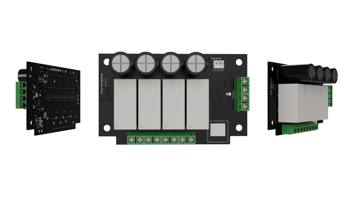
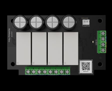
Superior MultiRelay Fibra provides four relay channels with potential-free contacts in a wired Ajax installation. It allows compatible external equipment to respond to configured commands or scenarios. Each channel’s load and behaviour are planned separately so the module fits the control requirements of the project.
Key features. At a glance.
4 independent relays
Automation scenarios

Remote control and configuration
Potential-free contacts
Operate with both AC and DC circuits
In-line connection with different types of devices
2 operation modes

Informative in-app notifications

Up to 516 mW1
Low power consumption
Protection against overheating
All relays are deactivated if at least one of them exceeds +80°C
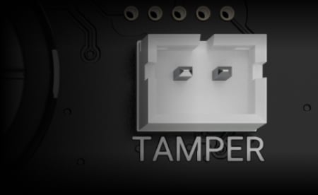
Tamper alarm
when installed into Case
Up to 2,000 m2
range of communication with an Ajax hub

Steady contact state3
The current state of contacts remains the same after a power outage


Power adjustment
- 1Maximum module consumption in the current exact specification. The older overview lists 0.18 W; calculate the full Fibra power budget.
- 2On a Fibra beam with U/UTP cat.5 4 × 2 × 0.51 mm copper cable, subject to the complete line calculation. Other cables and topologies have different limits.
- 3Optional setting for each relay in bistable mode. If disabled, contacts return to normal after a power loss.
Ajax product information ↗ · Superior MultiRelay Fibra specifications ↗
Protection in real places.
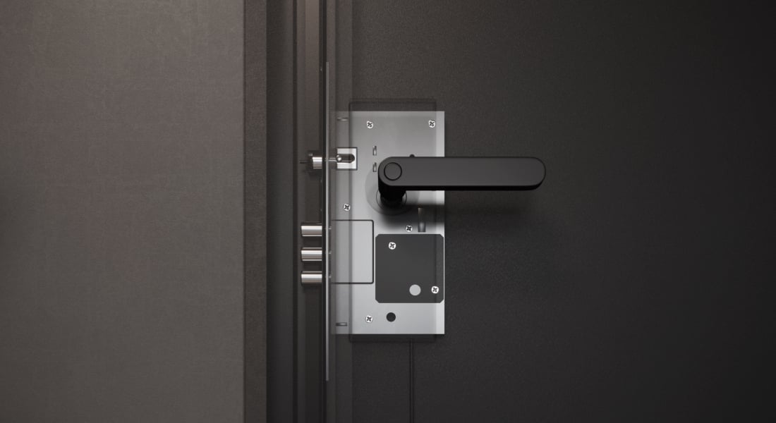





Four independent circuits. One module.

Configure each channel separately
MultiRelay provides four relays with potential-free contacts. Each can control a separate circuit with its own scenario and operating settings; several channels can serve one appliance where its wiring design requires it.
Dry contacts do not supply power. Each connected appliance needs the appropriate external supply and a checked circuit design.
Choose what each contact should do.
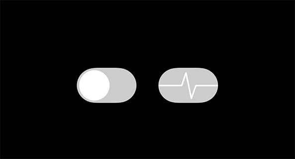
Pulse or bistable
Bistable mode holds the selected state. Pulse mode changes it for the configured duration and then returns.
The current exact specifications and manual allow 1 second to 2 hours per relay. The older overview says 10 seconds; use the current device settings.
Let the system respond to everyday conditions.
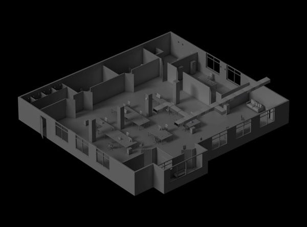
Separate scenarios for each relay
Use supported alarms, security-mode changes, schedules or environmental readings to trigger the configured channel. Suitable ventilation, lighting, access or heating equipment can respond as part of the same system.
The manufacturer’s examples require the appropriate detectors, controlled equipment and configuration.
Define the trigger and the return state.
A configured action, with a tested outcome
Choose the trigger, contact state and operating mode around the connected equipment. Test each scenario on the installed system, including what happens if power or the hub connection is lost.
A device that is offline misses its scenario trigger. A missed scheduled action does not automatically run when power returns. Humidity and CO₂ scenarios require LifeQuality; other triggers need their corresponding system devices.
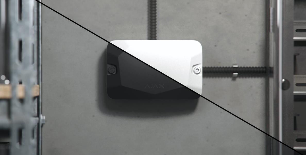
Fit the module inside a matching Case.
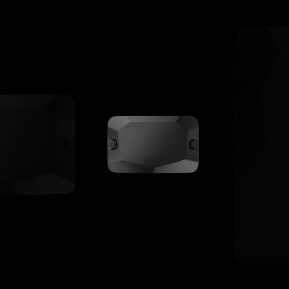
A protected, serviceable installation
The manufacturer identifies Case 2 for MultiRelay. The casing provides board holders, organised cable routing and a tamper board that connects to the module.
Case is sold separately. Check the current Case configurator for the exact combination; a common family illustration does not establish fit for every casing size.
One supervised wired connection.
Fibra communication
The four-wire connection carries data between the module and a compatible Ajax hub. Two-way communication, encryption with a dynamic key and device authentication help protect this connection. The module remains part of the hub’s system; it is not a standalone control panel.
Use the current compatibility list and supported firmware. The host’s device capacity and the line power budget still apply.
Calculate the complete Fibra line.
Power comes from the hub
MultiRelay operates from the Fibra supply at 8.5–26 V DC. Its current exact specification lists a maximum of 516 mW, with 21.5 mA at nominal voltage.
The product overview still shows 0.18 W. Use the exact specification and Fibra power calculator for the full line, cable, connected modules and operating conditions. A 2,000 m beam requires the specified U/UTP cat.5 cable; it is not a radio range.
Supervise the module and its connection.
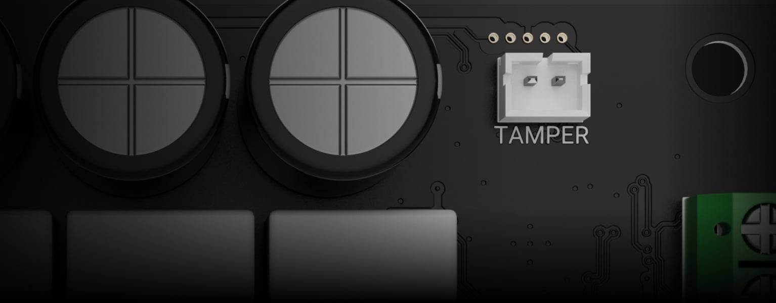
Case tamper alarm
The connected Case tamper board reports opening the enclosure or detaching it from its mounting surface.
This function requires the tamper board and the separately supplied Case.

Encrypted communication
Block encryption with a dynamic key helps protect the data exchanged by the module and its hub.
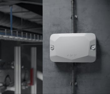
Regular connection checks
The hub polls the module and reports a missing connection or device fault.
Connection-loss timing is configurable. The 36-second example depends on the selected polling settings.

Identify the device and the event
Ajax notifications identify the module, event and assigned location so the responsible users can investigate.
Verify the communicating device
The hub checks device identity during communication and rejects commands that fail authentication.
Overheating opens all closed channels
If any relay exceeds its permitted temperature, all closed contacts open and an overheating notification is sent.
Treat line faults as a system design issue
Plan cable topology, protection, fault reporting and restoration with the compatible hub and Fibra modules.
MultiRelay is not a four-output Fibra line splitter or a substitute for line-protection equipment.
Designed for an installer-led project.
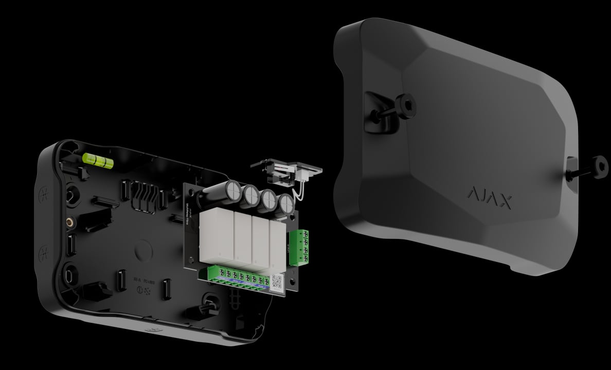
Mount inside Case
Fit the board in the matching Case holders, secure the enclosure and route the cables to the correct Fibra and relay terminals.
For indoor use at −10 to +40 °C. De-energise the appropriate circuits before work and keep low-voltage communication wiring and load wiring arranged to the installation design.
Make service events understandable.
Review events in PRO Desktop
The configured monitoring route can report faults, tamper events and connection loss with device and location information.
MultiRelay does not capture photographs. Any photo verification belongs to separate supported detectors and the configured monitoring system.
Find the right relay.
Compare Relay, WallSwitch and Superior MultiRelay Fibra. See what each switches, how it is powered and how many circuits it can control.
Compare automation relays →Every detail, in one place.
Communication
- Fibra communication technology
- Two-way system communication for the functions specified for this model.
- Line connection
- 4-core cable
- Connection
- to any point of the Fibra line MultiRelay can be installed behind the hub, detector, keypad, or siren.
- Fibra line length
- up to 2,000 m When using the U/UTP cat.5 twisted pair cable.
Lines connection
- Number of input lines
- 1 MultiRelay can be installed behind any Fibra device.
- Number of relays
- 4 Electrical appliances are connected to four relay outputs with dry contact.
- Cable length
- up to 2,000 m When using the U/UTP cat.5 twisted pair cable.
- Maximum switching voltage
- 30 V⎓, 230 V~ For each relay.
- Maximum switching current
- 5 A at 30 V⎓ 10 A at 230 V~ Maximum resistive load for each relay.
Key features
- Temperature protection
- When one of the relays exceeds the permissible temperature, all closed contacts automatically open. The user receives an overheating notification.
- Automation scenarios
- Adjusted in Ajax apps separately for each relay.
- Relay modes
- bistable pulse Adjusted in Ajax apps separately for each relay.
- Operating time
- from 1 second to 2 hours Adjusted for pulse mode in Ajax apps separately for each relay.
- State stability
- after power outage If the function is enabled, the current state of the relay contacts remains the same after a power outage.
Sabotage protection
- Tamper alarm
- MultiRelay has a connector to fasten the tamper board to the module. The tamper board is in Case that is sold separately.
- Protection against spoofing
- device authentication
- Connection loss detection
- after 36 s Between the hub and MultiRelay. It can be changed in hub settings.
Power supply
- Module’s operating voltage range
- 8.5−26 V⎓, up to 516 mW The hub powers the module. MultiRelay does not supply additional power to devices.
Board
- Dimensions
- 90 × 55 × 30 mm
- Weight
- 84 g
- Operating temperature range
- from −10 °C to +40 °C
- Operating humidity
- up to 75%
What’s in the box
- Superior MultiRelay Fibra
- Quick start guide
For your installation
- Selected as part of an installer-reviewed security or automation project.
- Fibra needs a supported hybrid control panel, checked cable type and topology, termination and a complete power budget. Existing alarm cabling is not automatically suitable.
- For indoor use only. It is recommended to install it in Case that is sold separately and available in several options.
Find the right protection.
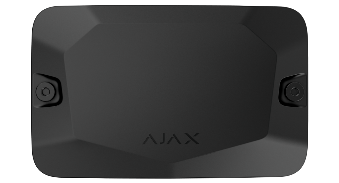
Case
Confirm Case 2 or another explicitly supported configuration.
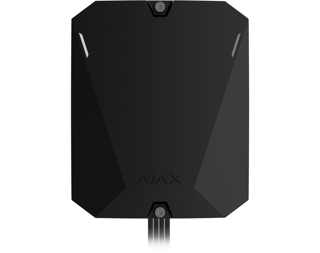
Superior Hub Hybrid 2
Plan a compatible hub, cable topology and full power budget.