MAKE IT YOURS
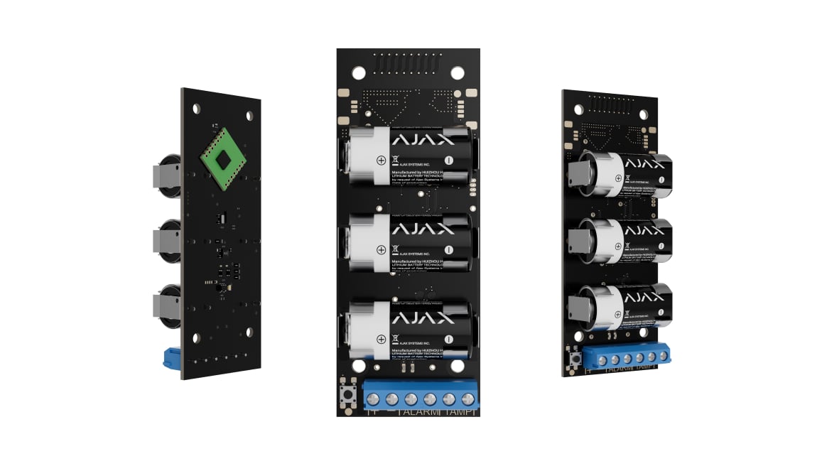
Transmitter.
Wireless module to integrate one third-party device into the Ajax system
Standards and certifications
Transmitter Jeweller · TR.Y.J. Manufacturer-listed marks; regional and installation conditions apply.
Give a wired device a wireless route.
Transmitter Jeweller connects a compatible third-party wired device to Ajax through alarm and tamper contacts. The compact battery-powered board fits inside a suitable enclosure, forwards events over Jeweller and can provide a limited 3.3 V supply. Contact type, power requirements and the intended alarm behaviour determine whether an existing device is suitable.
Key features. At a glance.
NC or NO
Alarm contact input
Separate tamper input
Report the connected enclosure
Pulse or bistable
Match the contact behaviour
14 event types1
Identify the signal
3.3 V DC2
Up to 125 mA for one device
Three CR123A batteries3
Power for the module
Up to 1,600 m4
Jeweller radio in open space
Up to 130 m5
Wired signal connection
Movement detection
Built-in accelerometer
Remote configuration
Set up in Ajax apps
100 × 39 × 22 mm6
Compact integration board
−25°C to +50°C7
Module operating range
- 1Available events depend on hub software and the selected sensor mode.
- 2This is not a 12 V supply. Check the wired device’s requirements.
- 3Operating life depends on the connected device and power settings.
- 4Enclosures, obstacles and interference reduce usable radio range.
- 5Specified with 24 AWG twisted pair; test the actual circuit.
- 6Allow at least 110 × 41 × 24 mm inside a suitable enclosure.
- 7The bare board needs a suitable protective enclosure.
Ajax product information ↗ · Transmitter Jeweller specifications ↗
Bring a wired contact into your Ajax system.

Wired signal, wireless reporting
Transmitter reads the alarm and tamper contacts of a compatible third-party wired device, then forwards events to an Ajax hub over Jeweller.
It is an input module for an Ajax system. It does not connect Ajax devices to a third-party control panel and does not provide relay control outputs.
Match the device’s contact behaviour.
Separate alarm and tamper inputs
Connect normally open or normally closed contacts, with a separate input for the third-party device’s tamper. Pulse and bistable modes suit different signal behaviour.
NC/NO contacts are supported; EOL resistance supervision is not a Transmitter function. The specification allows up to 130 m using 24 AWG twisted-pair cable. Test the actual connection.
Give the event its meaning
Select the event type so notifications and monitoring codes describe intrusion, fire, leakage, a panic button or another supported signal. A compatible configuration can instead use the input to switch arming modes.
Choose the sensor mode deliberately. Available events and arming functions depend on hub software; the module does not identify the attached device automatically.
Power the connected device correctly.
3.3 V output, up to 125 mA
Three preinstalled CR123A batteries power Transmitter. Its output can supply a compatible wired device at 3.3 V DC, up to 125 mA.
This is not a 12 V supply. Battery life depends on the attached device and its power mode; there is no universal multi-year figure.
Choose the power mode
The app can keep detector power enabled, turn it off while disarmed, or disable the output for an independently powered device.
Power mode affects alarm handling. In the documented always-powered pulse configuration, ALARM is processed at most once every three minutes. After rearming a detector powered off while disarmed, its first eight seconds are ignored. Follow the exact manual and test the response.
Check the radio link from inside the enclosure.
Encrypted two-way Jeweller
Events and configuration travel between Transmitter and a compatible Ajax hub or assigned range extender. The stated open-space distance is up to 1,600 m.
The third-party enclosure, metal and nearby equipment can reduce coverage. Test with the final enclosure closed and use matching regional radio versions. Transmitter does not work with ocBridge Plus or uartBridge.
Supervise movement and the wired tamper.
Two different sources of protection
The module’s accelerometer reports movement when enabled. Its TAMP terminals can report the connected device’s enclosure tamper, if that device provides one.
The hub also supervises the module’s radio connection. A nominal 36-second loss report depends on polling settings; it is not a fixed guarantee for every installation.
Fit the module to the existing device.
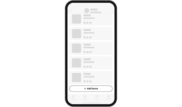
Add by QR code
Pair Transmitter in the Ajax app, then name the attached device and assign its room.
Find the right wired integration module.
Keep suitable wired detectors when moving to Ajax. Compare signal inputs, detector power and whether the module can also control equipment.
Compare wired integration →Every detail, in one place.
Communication
- Jeweller communication technology
- Two-way system communication for the functions specified for this model.
- Radio communication range
- up to 1,600 m Between the integration module and a hub (or a range extender) in an open space.
- Encrypted communication
- Encrypted device communication.
- Frequency hopping
- To prevent radio interference and jamming.
Wired devices connection
- Supported configurations
- Transmitter Jeweller has two pairs of terminal inputs for tamper and alarm sensor connection. Alarm and tamper inputs can be used to connect a wired device using the AATT (Alarm Alarm Tamper Tamper) scheme.
- Terminals for wired device connection
- “+ –” — 3.3 V⎓ power supply output for connecting a wired device.; ALARM — inputs for connecting a wired device.; TAMP — inputs for connecting a tamper of a wired device.
- Third-party device contact states
- NO, NC
- Tamper contact states
- NO, NC
- Cable length
- up to 130 m When using 24 AWG twisted pair cable.
- Operating modes
- pulse, bistable
- Sensor modes
- Notify of alarms, Switch arming modes
Sabotage protection
- Protection against spoofing
- integration module authentication
- Accelerometer
- alert when the integration module is moved
- Tamper alarm terminals
- Terminals for connecting to a wired device tamper (if applicable).
- Detection of communication loss with integration module
- after 36 s Detection time depends on the Jeweller or Jeweller/Fibra settings.
Power supply
- Battery
- 3 × CR123A Pre-installed. Battery life depends on the power consumption of a connected wired device.
- Output to the connected wired device
- 3.3 V⎓, up to 125 mA One power supply line from Transmitter Jeweller.
Board
- Dimensions
- 100 × 39 × 22 mm
- Weight
- 74 g
- Operating temperature range
- from −25 °C to +50 °C
- Operating humidity
- up to 75%
- Electric shock protection
- Class III
What’s in the box
- Transmitter Jeweller
- 3 × CR123A battery (pre-installed)
- Installation kit
- Quick start guide
For your installation
- Selected as part of an installer-reviewed security or automation project.
- Confirm the supported control panel, device software and regional radio version; test coverage at the final installation position.
- Transmitter Jeweller should be installed inside the wired detector enclosure. The module requires a minimum space with dimensions of 110 × 41 × 24 mm. If it is not possible to install Transmitter Jeweller within the detector’s enclosure, any available radiotransparent casing can be used.
Find the right protection.
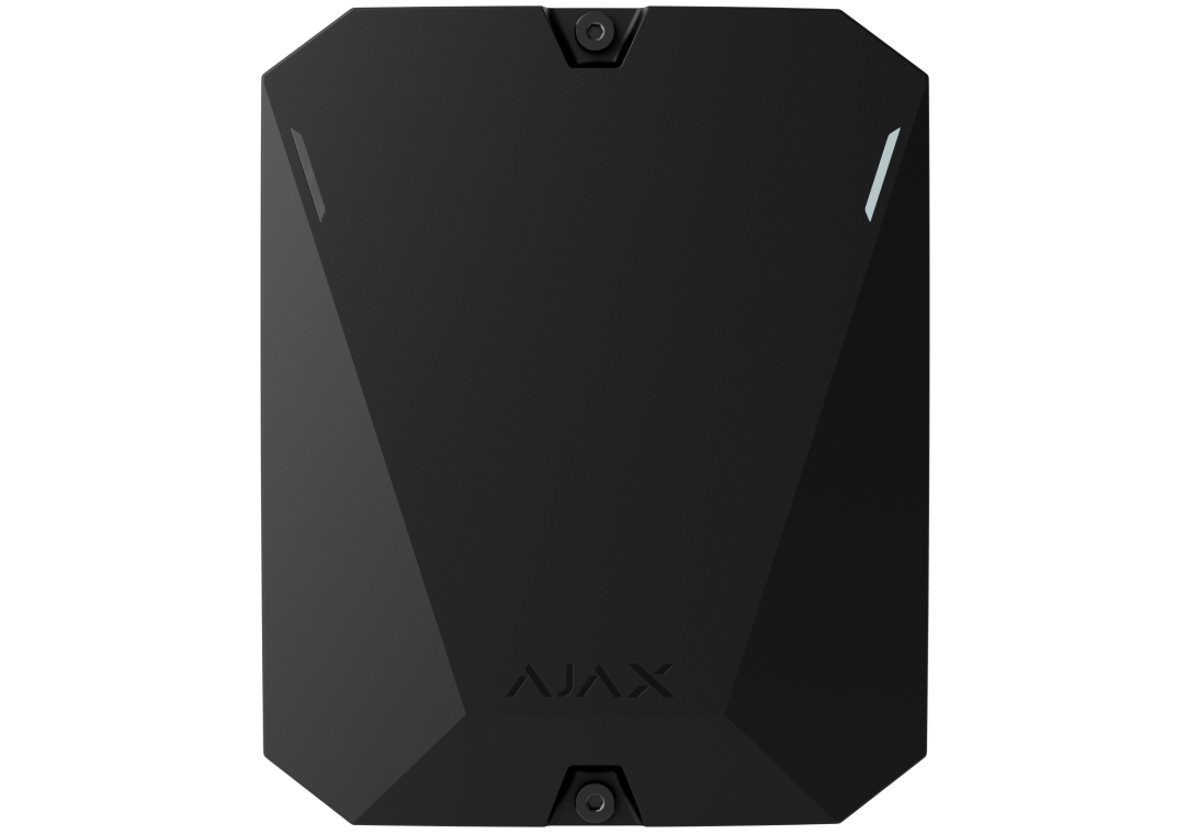
MultiTransmitter Jeweller
Compare an 18-zone module with mains power and supported EOL supervision.

Takeover Module Jeweller
Takeover handles listed wireless protocols instead of wired contact inputs.